C2584 User Manual – Legacy Product
Read First!
If you use the Interface MIC input to connect the C2584, remember to switch OFF the PHANTOM POWER! Phantom power may damage the output of the C2584!
DO NOT USE unbalanced cables to connect the C2584 – you may get the level and phase issues. DO NOT connect the unbalanced cables to the OUTPUT of the C2584 – you may damage the C2584 output!
If you use the interface MIC input set the GAIN to a minimum. DO NOT use the MIC input PAD function. PAD will deteriorate the Signa-to-Noise ratio! Use only the native line input if possible.
Some 500 racks may have extra features, such as internal signal routing and patches. Make sure that you have SWITCHED OFF all extra features. Refer to your 500 rack MANUAL.
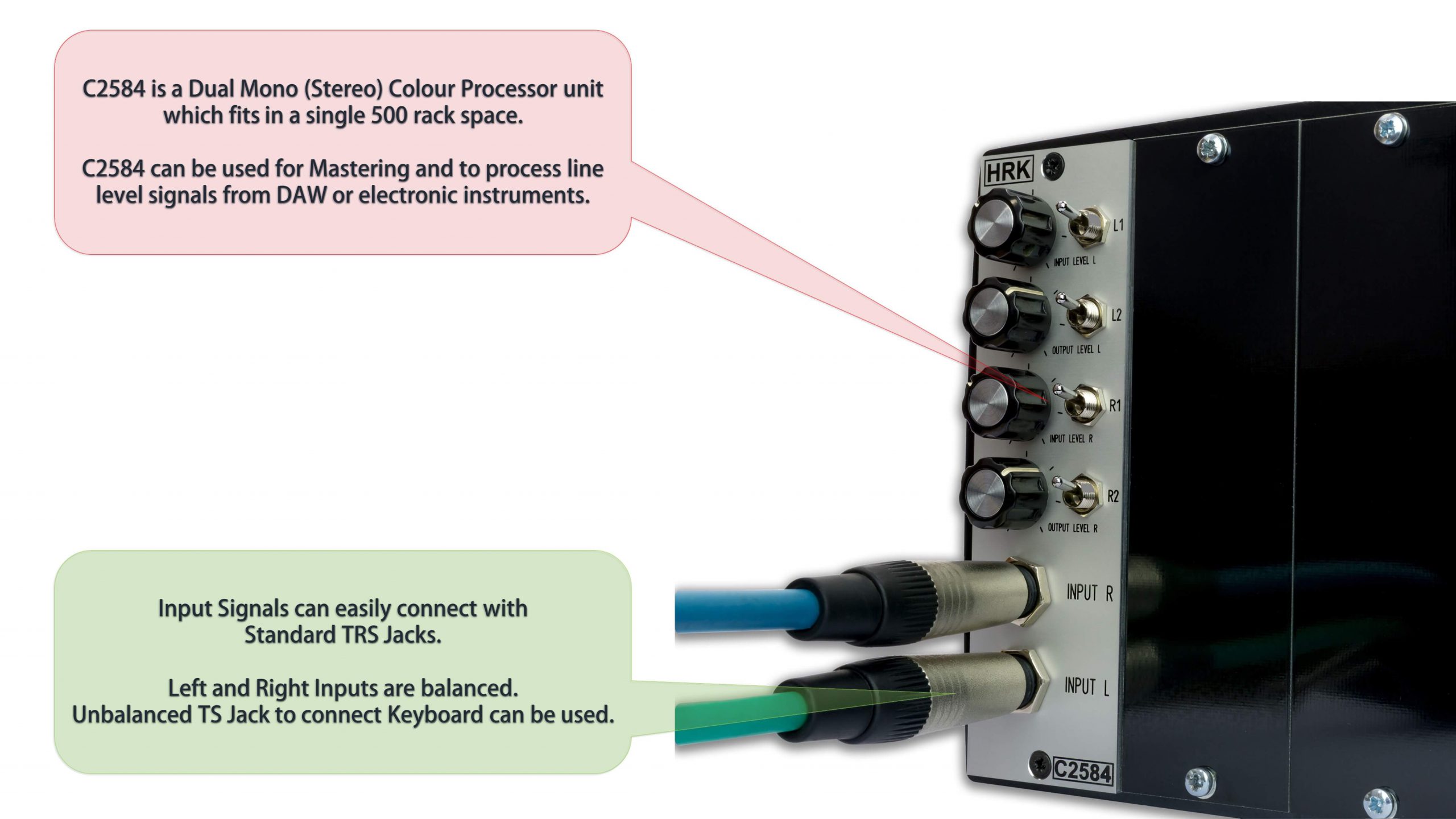
The C2584 is not a DIYRE Palette replacement. The C2584 is a dual-mono/stereo unit that can be used to process the stereo signals, such as DAW final mix or other line-level signals.
There is no BLEND option available, two colours in each channel are connected in series. All knobs are the level control knobs, which means that in a minimum left position the signal will disappear completely.
There is no DIYRE Palette type drive/cut function available. Input Level knob sets the level which is sent to colours modules and the Output level knob controls the level from the colour modules.
The levels between the Left and Right channels are very well matched, down to 0.25dB. The mismatch can appear if the colour modules which apply the gain are installed and engaged. Some colour modules may introduce the phase shift or phase inverse.
Use the Output Level knobs to match the channels with you DAW VU meters.
The C2584 is professional studio equipment. The user should read and learn the basics of audio engineering before the use of any studio equipment.
Improper use or lack of basic knowledge will result in unwanted results or may be a cause of damage to your studio equipment.
General
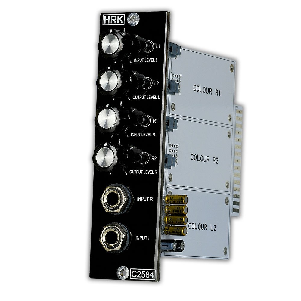
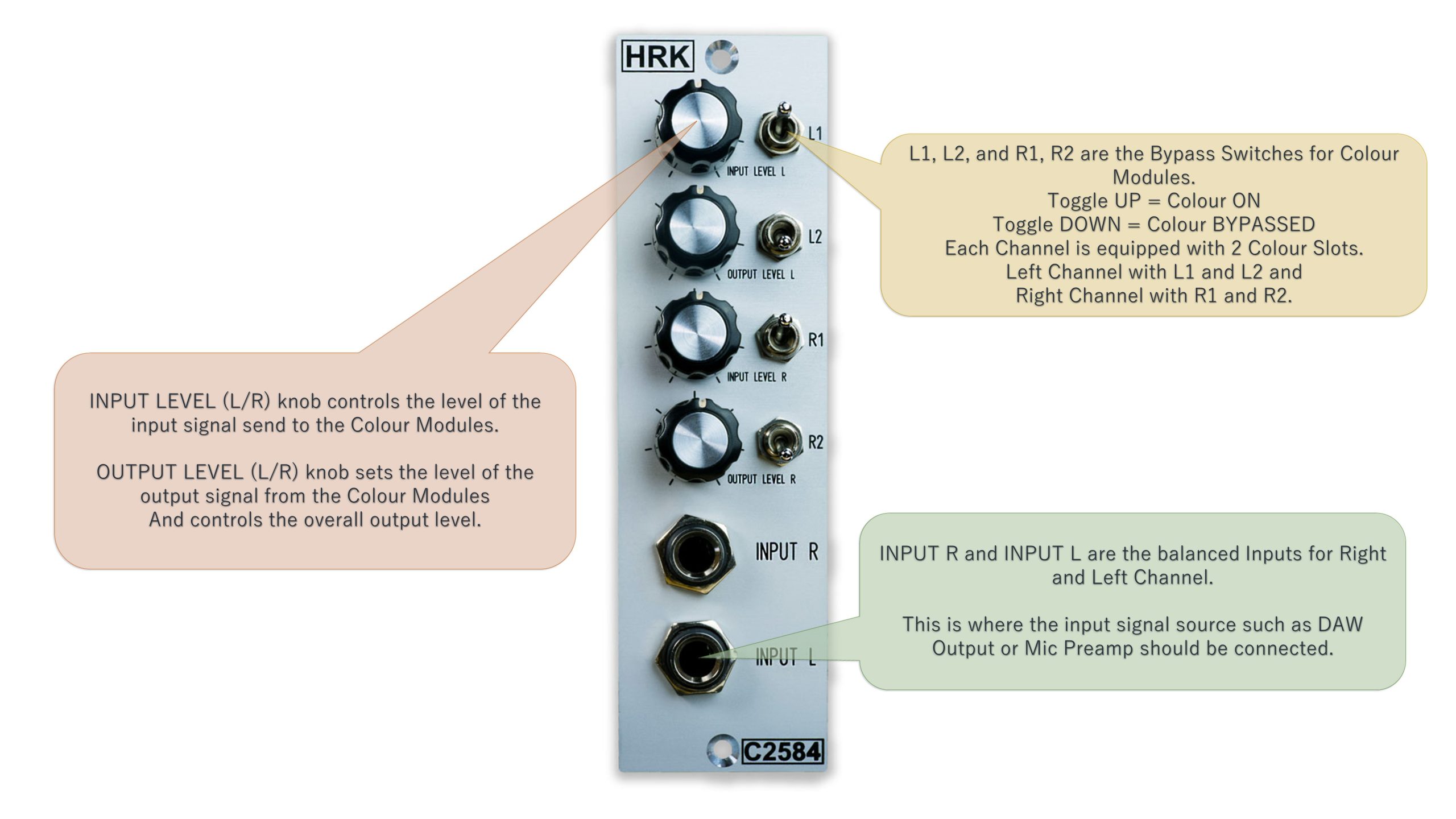
The C2584 is dual mono (stereo) colour processor unit with four colour modules slots. Each independent channel has two colour slots connected in series. Each colour module can be engaged or disengaged by the designated bypass switch. Each channel has the INPUT LEVEL knob and OUTPUT LEVEL knob. The input stage of each channel has a fixed gain of +12dB. INPUT LEVEL knob controls the signal level sent to the colour modules.
The INPUT LEVEL in not a GAIN knob, the gain of the input stage is fixed to +12dB. INPUT LEVEL knob sets the signal from NO SIGNAL (0) to the maximum level of an available signal. In the minimum position of the INPUT LEVEL knob, the signal will be cut-off completely. To avoid over-driving the C2584 unit or the next stage, such as the interface, reduce the output level from the DAW by -12dB. If required, the input signal level from the DAW can be increased to achieve the desired saturation of the colour modules.
The output stage provides an additional +6dB of fixed gain. The OUTPUT LEVEL knob controls the overall output signal level from the C2584 unit. The OUTPUT LEVEL knob sets the signal from NO SIGNAL (0) to the maximum level of the available signal. In the minimum position of the INPUT LEVEL knob, the signal will be cut-off completely.
First Use of C2584 – Follow this procedure step-by-step:
- Set all knobs to a maximum.
- Reduce the level from the DAW to -20dB
- Set all switches downwards (C1-4)
- Make sure that inputs and outputs are connected to correct TRS sockets on the front panel and to the correct XLR connectors at the back of the 500 rack
- Play the 1kHz test signal or track
- Confirm that the signal pass from inputs to outputs – stereo operation
- Turn INPUT LEVEL knobs to minimum
- Play the music track
- Switch the C1-4 upwards
- Slowly turn up the INPUT LEVEL knobs to achieve the desired level of colour module saturation
- Use the C1-4 switches to A/B the signal
- Use the OUTPUT LEVEL knobs to reduce the output level from the C2584
Why you should not use the resistor mic input PAD.
The most common way of adding the Line Input functionality to the mic input of the Interface is the mic input PAD.
The mic input PAD is nothing more than resistors added on the input of the microphone preamplifier.
The signal is attenuated and again amplified by the microphone preamplifier. As a result, the signal-to-noise ratio is worsening.
Also, the impedance matching between the source and the mic preamp is disrupted causing unwanted frequency response issues.
Signal Routing (Each Channel).
Colour modules are connected in series. No parallel signal routing is possible. Signal will be first affected by the first colour module – L1 or R1 and passed to the next colour module inserted in the colour slot L2 or R2.
The increase of the input signal level controlled by the INPUT SIGNAL knob will have the biggest impact on the first colour module. Therefore, it is recommended to insert the drive dependent colour modules ( Discrete Saturation, British Console, Soviet Pentode) in the first slot: L1 or R1.
The drive dependent colour modules can also clip the signal, limiting the signal level passed to the next colour module. Signal conditioning colours (DOPA520, Classic VCA, British EQ) should be installed in the second colour slot – L2 or R2.
The signal from the second colour slot is passed to OUTPUT LEVEL knob and then to the C2584 output. The OUTPUT LEVEL knob controls the total output level from the C2584.
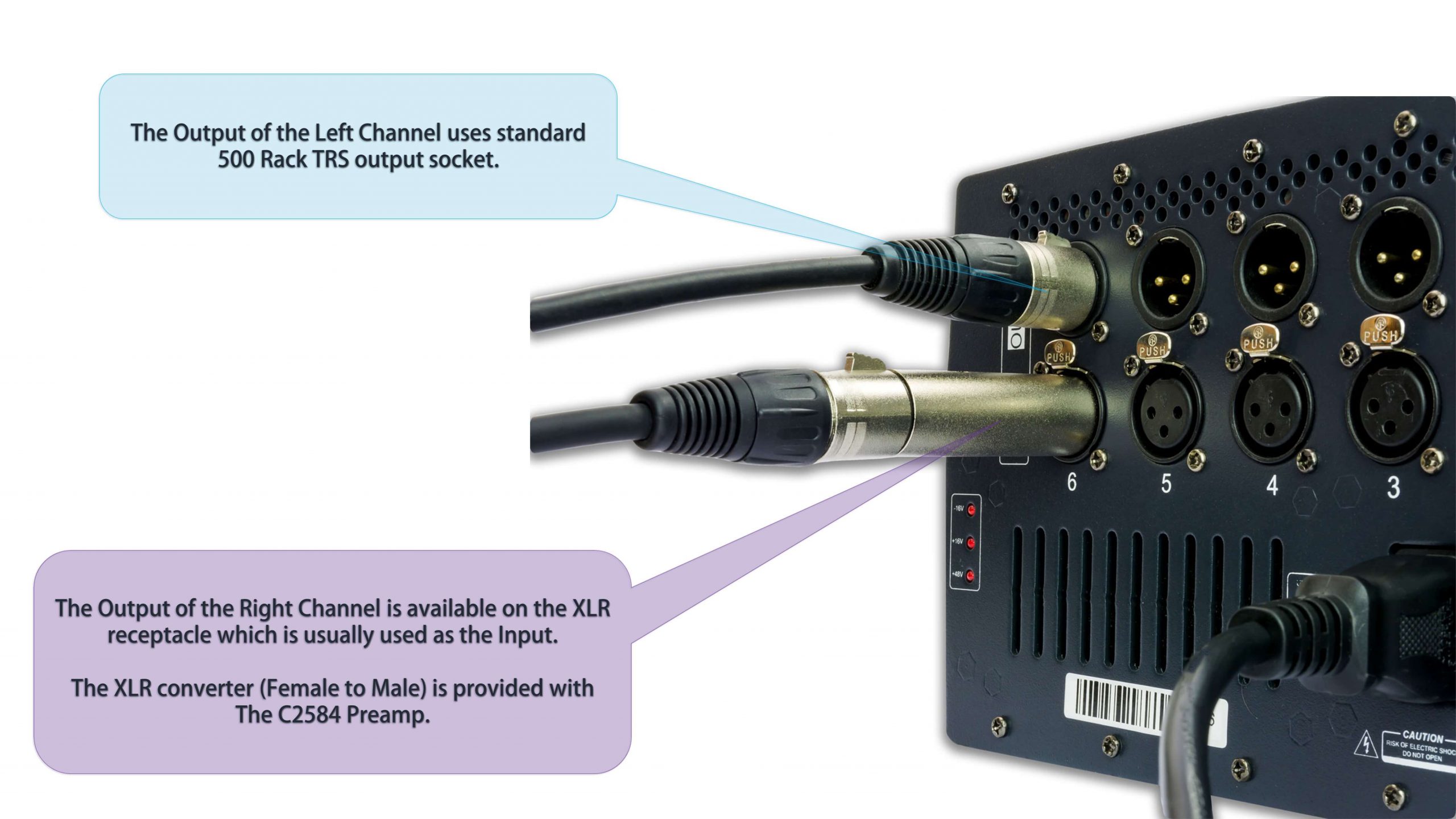
Inputs of the C2584 are provided by the balanced TRS sockets on the front panel. Stereo outputs of the C2584 are provided by the standard 500 rack XLR connectors located on the rear panel. The XLR adapter is included with the C2584.
Outputs of the C2584 are provided by the standard 500 rack XLR connectors located on the rear panel. The XLR adapter is included with the C2584.
How to Use the C2584?
The C2584 can be used for mastering the stereo track or to record the signal from an instrument such as a keyboard. The total gain from input to output is +18dB, with bypassed colour modules and with all knobs set to maximum.
Before the use of C2584 turn all knobs to 12 o’clock position. Reduce the output level of the DAW by -12dB. Make sure that all switches are in a LOW position (colour modules bypassed). Play the test 1kHz signal from DAW. Confirm that the signal returns to the DAW system.
Engage selected colour modules, using the INPUT LEVEL knob to adjust the level of saturation for colour modules. While increasing the input level with the INPUT LEVEL knob control the DAW signal meter and reduce the signal with the OUTPUT LEVEL knob to avoid clipping of the interface input stage.
Some colour modules can reduce the overall output signal level. Some clipping colour modules, such as Discrete Saturation, may act as a primitive limiter. Further increase of the input signal will not increase the overall output signal level.
If you use the interface MIC input set the GAIN to a minimum. DO NOT use the MIC input PAD function. PAD will deteriorate the Signal-to-Noise ratio! Use only the native/active line input if possible.
Cheap, two channels of audio interfaces emulate the Line Input function by using the PAD attenuator with the standard MIC input. It is better to use the MIC input with minimum GAIN and reduce the output level from C2584 if necessary.
Such a solution will result in a better Signal-to-Noise ratio and overall better sound quality.
The above procedure can be used for mastering and recording.
Matching the level between channels.
Set the input gain of the interface to a minimum. Disengage all PADs and other features on the interface.
Disengage all colour modules – all switches in the DOWN position. Set all knobs in 12 o’clock position. Send the -10dB test tone signal. Read the signal level from the DAW VU meter.
The level between channels should be equal. Engage the colour modules. Switches set in UP position.
If you see the level mismatch between the channels, tweak the Output Level knobs of left and right channel to match the levels.
Use your DAW VU meter and observe the change in signal level.
Using the C2584 in Mono Mode.
The safest way to connect the two channels of the C2584 in series is to use the XLR to TRS cable and connect the output of channel1 to the input of channel2.
Any other attempts to manipulate with the C2584 edge connector or to use the specific custom connection features (internal routing switches, extra inputs or outputs and other custom features) for your 500 rack may result in unwanted results or may cause damage of the C2584.
In a mono mode, 4 colour modules will affect the signal. It is important to understand that colour modules will be controlled in pairs. Please refer to the signal flow diagram of an individual channel.
C2584 in mono mode will work differently than C544. C2584 in a mono mode can’t replace the C544.
The C544 has a separate gain/trim knob for each colour module and the C2584 has controls for each pair of colour modules.