C572 User Manual
[C572 PRO / C572 Silver Plate – Legacy Products]
Read First!
If you use the Interface MIC input to connect the C572, remember to switch OFF the PHANTOM POWER! Phantom power may damage the output of the C572!
DO NOT USE unbalanced cables to connect the C572 – you may get the level, phase and ground loop problems. DO NOT connect the unbalanced cables to the OUTPUT of the C572 – you may damage the C572 output!
Each Colour Module section contains the opamp based Drive/Trim circuitry which provides the gain of up to +20dB. This means that the opamps may be overdriven even if the colour modules are not engaged.
If you hear the distortions, even if the colour modules are disengaged, reduce the level of the signal from DAW. Remember, MORE does not mean BETTER!
Some colour modules require only little gain or drive to achieve great results; other colours have to be driven a bit harder. DRV knob has a range, which means that it DOES NOT have to be on the MAXIMUM all the time… 😉
If you use the interface MIC input set the GAIN to a minimum. DO NOT use the MIC input PAD function. PAD will deteriorate the Signal-to-Noise ratio! Use only the native/active line input if possible.
Cheap audio interfaces emulate the Line Input function by using the resistor PAD attenuator in series with the MIC input. It is better to use the MIC input with minimum GAIN and reduce the output level from C572 if necessary.
Such solution will result in a better Signal-to-Noise ratio and overall better sound quality.
The C572 is professional studio equipment. The user should read and learn the basics of audio engineering before the use of any studio equipment.
Improper use or lack of basic knowledge will result in unwanted results or might be a cause of damage to your studio equipment.
GENERAL
The C572 is a Mono Parallel Saturation Processor with three Colour Module slots. The C572 is fully compatible with the DIYRE Colour Format and The DIYRE Colour Modules. All DIYRE Colour Modules are compatible with the C572.
The C572 is designed to process the line-level signals from the DAW system or the other line-level source. The C572 is not suitable for use with the microphone or any other low-level signal source.
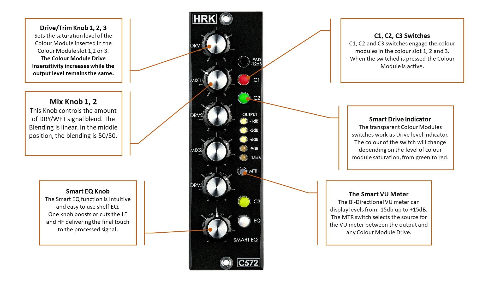
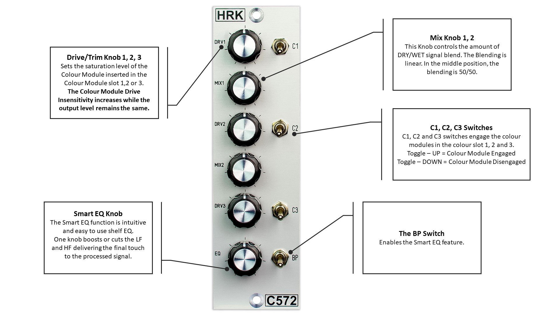
Each colour slot has an independent Drive/Trim control knob section and the Colour Module bypass switch – C1, C2, C3.
To engage the colour module, push-in the bypass (C1, C2, C3) switch. If the colour module is inserted into the colour socket the signal will pass. If the colour module is not present or not inserted correctly, the signal will be interrupted – no sound.
Main LED Bar Signal Level Meter
| Meter LED Bar Reading | Normal Mode Signal Level – Bottom to Top | Inverse Mode Signal Level – Top to Bottom |
| -1dBu | -1dBu | 0dBu |
| -3dBu | -3dBu | +3dBu |
| -6dBu | -6dBu | +6dBu |
| -9dBu | -9dBu | +9dBu |
| -15dBu | -15dBu | +15dBu |
The meter is calibrated with Audio Precision Test Equipment in dBu units.
The use of phase inverting colour modules – Important for correct operation!
If you planning to use the colour modules listed in the table below in slot 1 or 2 you should set the phase inverse jumper to the correct position. Please check the spec if you use the colour modules supplied by other manufacturers.
The list of a phase inverting HRK Colour Modules |
| Easy EQ Ge – No longer available |
| Easy EQ Si – No longer available |
| Soviet Pentode – Available |
| US Pentode – Available |
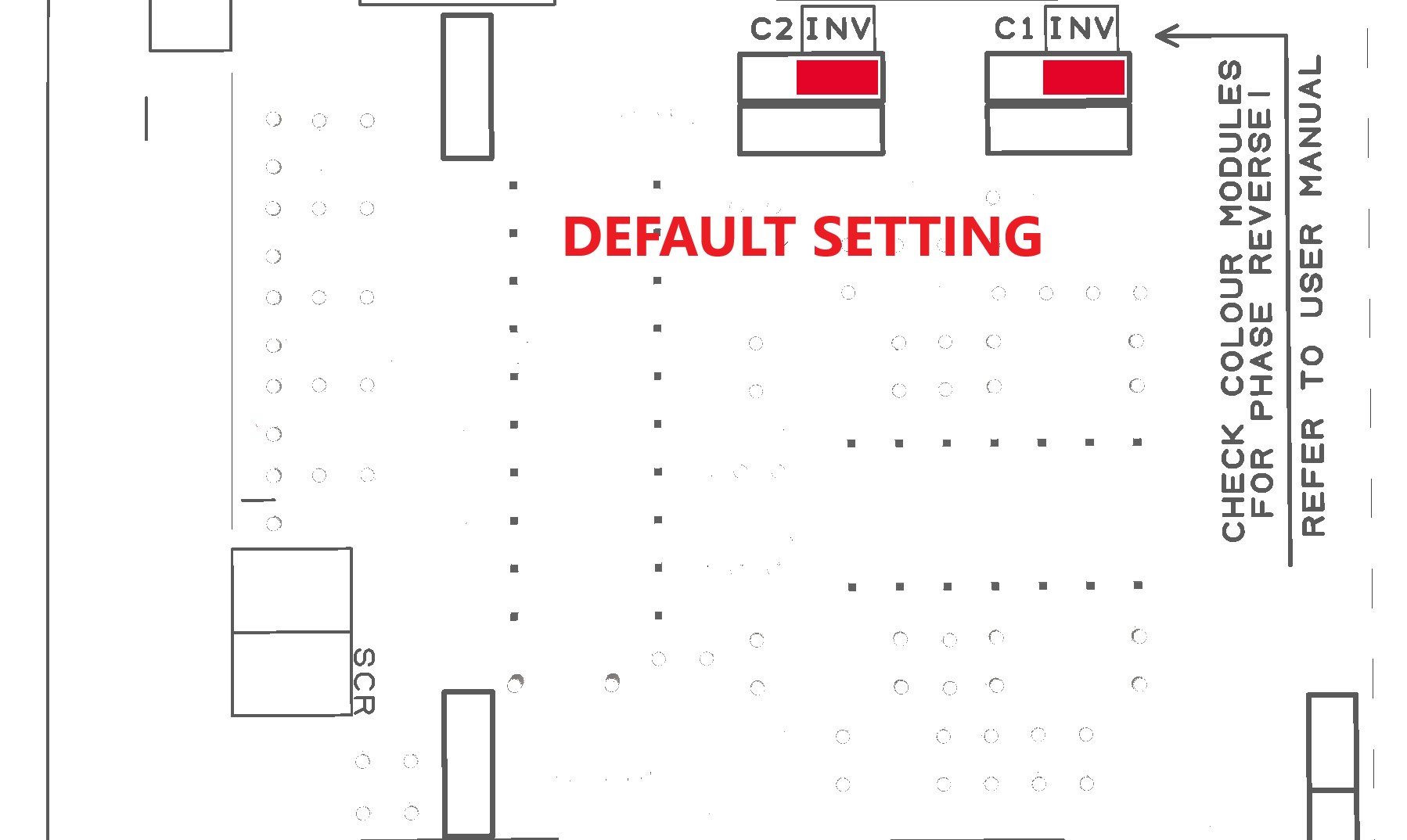
If you going to use any of the HRK colour modules listed above or colour modules from another supplier that inverse the phase of the signal, you should change the position of the jumpers from the default non-inverting setting as shown on the picture below:
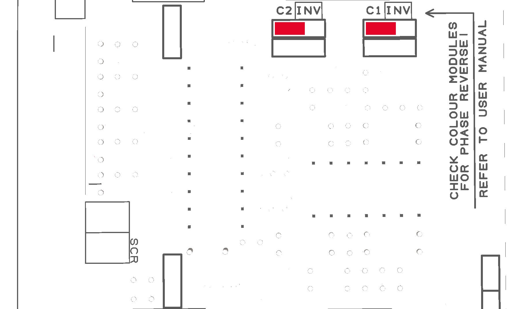
To the position which will inverse the phase as shown in the next picture:
If you planning to insert the inverting colour module to slot 1 you should change the jumper position for C1 and if you using slot 2, change the jumper C2. If you using inverting colours in both slots you should change both jumpers.
This is necessary, otherwise, you may experience the phase cancellation in the 50/50 position of the blending MIX potentiometers.
The Drive/Trim Operation – Each Colour Module – The DRV (1, 2, 3) Knob
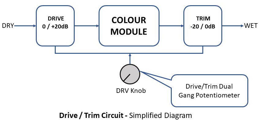
Each Drive/Trim Colour Module section has the independent active Drive circuitry with +20dB gain which can be used to saturate the colour module. The Trim part of the section is placed after the colour module.
The Drive/Trim is using a dual-gang potentiometer. If the Drive gain increases the Trim reduces the signal from the colour module by approximately the same dB value. As a result, the absolute output signal level remains equal to the input signal.
Some colour modules can clip the signal due to the limited headroom. Saturation colour modules, such as Discrete Saturation, British Console or Solid State Console, may act as simple limiters. Further increase of the input signal will not increase the overall output signal level from the colour module!
In such a case, the output level from the colour module may be lower than the input level, while the distortions level will increase.
The Drive/Trim knobs should be used with caution. Some colour modules will cut off if driven too hard. In severe cases, a high signal level may damage the colour module.
Important Note!
The most common mistake made by the users so far is overdriving the Colour Processors with a too high-level signal sent from the DAW. Each colour module stage in the C572 provides +20dB of Gain. This means it increases the input signal level up to 10 times. Please reduce the signal sent to the C572! The C572 is not a vintage transformer or valve preamp which will sound good if driven hard… It is a piece of modern studio equipment that has a headroom limit. It will clip at some point and it will produce audible, most likely unpleasant distortions.
If you hear the distortions, even if the colour modules are disengaged, reduce the level of the signal from DAW. Remember, MORE does not mean BETTER!
The Blending of the DRY/WET signal – MIX (1, 2) Knob
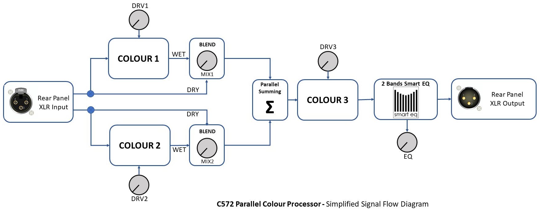
First two colour modules have the MIX knob which allows blending the DRY and the WET signal after setting the desired level of saturation with the DRV knob.
This feature is very useful if the effect produced by the colour module is a bit too harsh or the signal is overdriven on purpose to achieve creative results with audio material. In the 12 o’clock position the DRY/WET signal ratio is 50/50.
The third colour module slot is equipped only with the Drive/Trim DRV knob and it can be used for colour modules like the Discrete Line Driver or the British Driver to provide fixed saturation to the summed signals from colour module 1 and 2. Please take a moment to study the signal flow diagram.
The C572 will produce always the same equal signal level regardless of the MIX1 or MIX2 knob position. The total gain of the C752 with bypassed EQ is 0dB within a maximum of +/- 1dB tolerance depending on the potentiometer setting. Some colour module may increase or reduce the level of the signal depending on the type and use of the colour modules.
The first use of the C572 – Important!
-
Set all Drive/Trim knobs to a minimum – max left
-
Set all Blend knobs to a minimum – max left
-
Reduce the level from the DAW to -20dBu
-
Set the EQ Knob to 12 o’clock – 0dB
-
Set all switches downwards (C1-3, EQ BP)
-
Make sure that input and output is connected to correct sockets on the back of the 500 rack
-
Play the 1kHz test signal or 1kHz track and confirm that the signal pass from input to output
-
Use the C1-3 switches to engage the colour modules
-
Use the DRV (1-3) knob to achieve the desired level of saturation.
-
Use the MIX (1-2) knob to achieve the desired level of Blending between the DRY and WET signal.
-
Use the C1-3 switches to A/B the signal
-
Switch the BP switch upwards to engage the Smart EQ, turn the EQ knob left or right to achieve the desired EQ response
The Smart EQ
The smart eq circuit is made of two independent HF and LF blocks to ensure that bands have no interaction. Each band has two frequency settings which can be selected by the jumpers.
The picture below shows the location of the jumpers. The label next to the jumper indicates the frequency which will be selected when the jumper is inserted.
The table below shows the frequencies depending on the jumpers settings.
|
|
JUMPER IN | JUMPER OFF |
| LF | 80Hz | 160Hz |
| HF | 6kHz | 10kHz |
The Smart EQ can boost or cut the signal like a typical EQ. One knob dual gang pot controls both the HF and LF. The EQ can produce the so-called smiley curve which is the most common way of enhancing the tone of the signal. The maximum boost or cut is +/-8dB.
© 2024 HRK Shop
User Information. This page uses cookies files to process the orders and deliver a better user experience.


