MP568C USER MANUAL
[ LEGACY PRODUCT]

READ FIRST!
If you use the Audio Interface microphone input to connect the output of the MP568C, remember to switch OFF the PHANTOM POWER! Phantom power may damage the output of the MP568C!
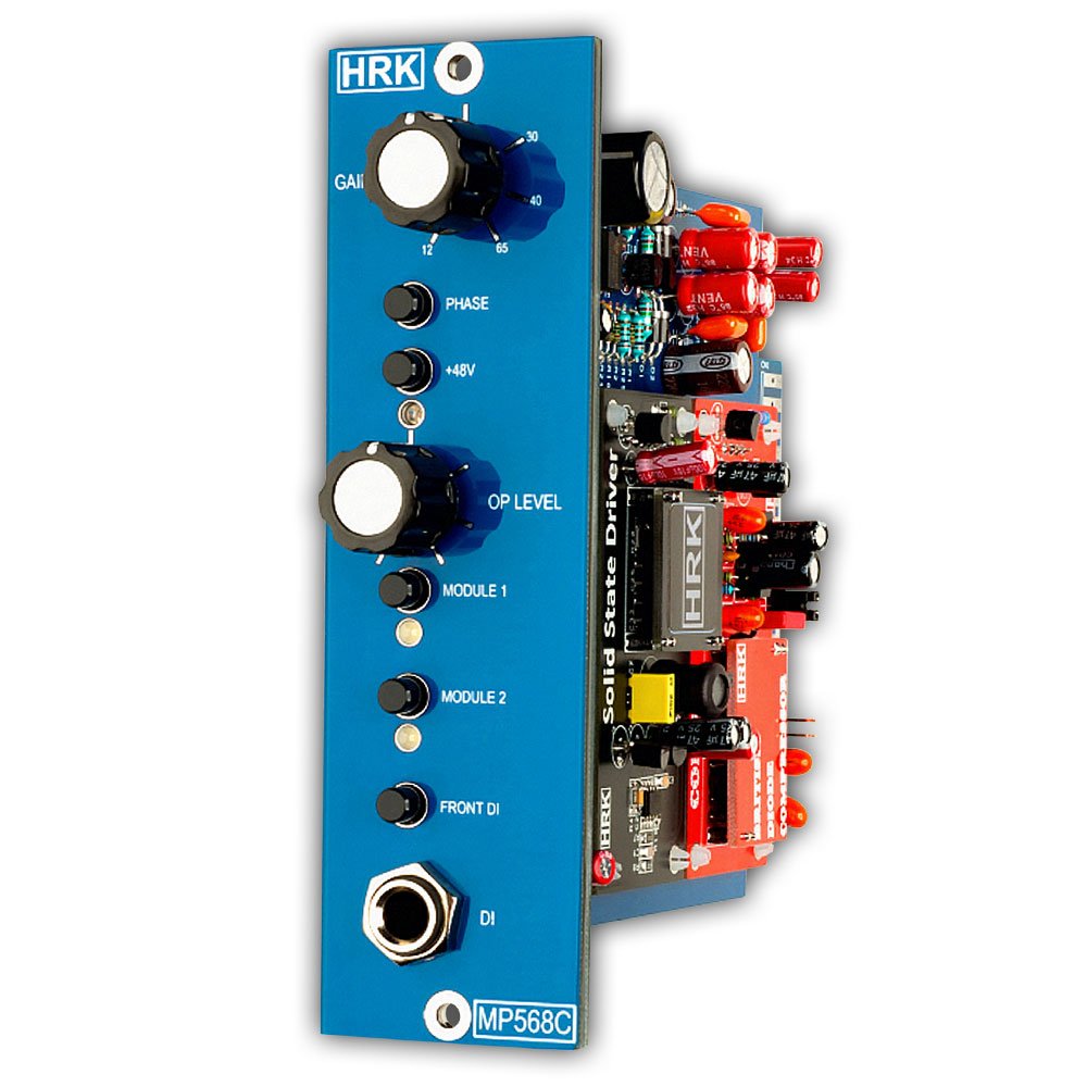
The MP568C is a studio-grade professional microphone preamplifier with 2 Colour Modules slots. The MP568C is fully compatible with the DIYRE Colour Format and DIYRE Colour Modules.
The MP568C Microphone Input should be used for recording low-level signals from dynamic or condenser microphones.
The MP568C principles of operation are different from how the DIYRE Palette works. The MP568C cannot be used as a replacement for the DIYRE Palette.
The behaviour of Colours may vary depending on settings and configuration. Colour Modules from a different manufacturer may behave differently when compared to HRK Colour Modules. All HRK Colour Modules are compatible with DIYRE Colour Module Format.
Improper use of the MP568C may create unwanted results, such as noise or audible distortions. Users should learn the basics of audio engineering before the use of any professional studio equipment.
THE FIRST USE OF MP568C – follow this procedure step-by-step!
1. Set the GAIN Knob to a minimum (max left)
2. Set the OUTPUT level knob to maximum (max right) – Default Position
3. Disengage all Colour Modules – Switch C1 and C2 toggle positioned downwards.
4. Connect the condenser microphone to rear panel XLR connector
5. Switch the LINE/MIC switch to MIC position
6. Switch ON the phantom Power – toggle UP – check the 48V LED – it should be ON.
7. Set the input gain of the audio interface to a minimum
8. Switch OFF any PAD or input attenuator on the interface.
9. DO NOT use the line input with a built-in PAD attenuator – it may worsen the quality of the recording.
Increase the gain level with the GAIN knob until the desired level of the signal is achieved. Observe the DAW VU meter. Do not use an excessive amount of gain! Do not overdrive the input of the audio interface.
Check that the loudest transients will not overdrive the signal chain! Gain between the +20dB and +30dB is sufficient for most of the standard modern condenser microphones. Make the test recording before proceeding any further.
How to get the best results from the MP568C and the Colour Modules – IMPORTANT!
The Colour mic preamp should be used in a bit different way than the typical mic preamp. It is recommended to spend some time and use the colour preamp solo, connected directly to the audio interface, to learn how to get the best results from the colour preamps and colour modules.
Users familiar with vintage mic preamps, such as the NEVE 1073, know that increasing the gain of the mic preamp and reducing the output level from the preamp will produce a warm and saturated sound. It is true because the mic preamp becomes a source of the harmonics when driven with higher gain or higher signal level. The output stage and the output transformer plays an important role as well. This is why advanced users try to saturate the output stage and use the PAD or signal attenuators to prevent overdriving the interface.
Such an approach will not work with colour preamps! The MP568C is a solid-state, ultra-low noise and clean preamp. It is a platform for colour modules. Overdriving the mic preamp or the output won’t produce any “interesting” results… apart from the potential damage of the colour preamp and the interface.
The source of the harmonics are the colour modules which can be plugged in the colour preamp. Therefore, the role of the colour mic preamp is to produce a healthy and clean signal which will be processed by the colour modules.
Each colour module is different and will require a different signal level to produce optimal results. If the colour module is driven too much, the result will be bad… there is a sweet spot for each colour module and the user should learn how to find it.
To get the best results from the colour modules the GAIN knob has an uneven spread of gain on the knob scale. This helps to control the saturation of the colour modules and is optimised for condenser microphones and the Line level signals.
Remember, using too much gain or feeding the preamp with a high-level signal or pushing the output of the preamp to its limits will not produce good results!
The GAIN Knob
Mic preamps that don’t use the colour modules have (more or less) equally spread of gain range/scale around the gain knob. Because the Gain knob in the colour preamps is used to drive the colour modules the gain range up to +35dB occupies most of the gain range/scale.
While this might be unusual at first glance and sometimes against the “old” habits, it helps a lot to accurately set the saturation of the colour modules, especially when used with condenser microphones which do not require a lot of gain. In such an application, a higher resolution of the scale for the lower values of the gain is much more useful.
The gain range from +40dB up to +65dB will be used most often with the dynamic microphones which require more gain. Since the dynamic microphones are far less sensitive than the condenser microphones, the accumulation of the gain should not cause the problem.
If the dynamic microphone is used with the guitar cabinet or another loud source, it will produce a signal level similar to the condenser microphone.
User should learn how to use the colour mic preamp and the colour modules correctly. The best way is to use the colour mic preamp solo (without any additional studio equipment in series), connected directly to the audio interface. Use different microphones and different sound sources. Make a few test recordings and find the best setup.
How to use Colour Modules
After establishing optimal recording level from the MP568C engage (upwards position) the C1 or C2 switch. The GAIN knob controls how hard the colour module is driven. More gain means more drive. There is no other way to control how hard the colour modules are driven.
Increase the GAIN gradually until the desired saturation of the colour modules is achieved. It is not recommended to use too much gain while the OUTPUT knob is set to low levels. Such a setting may overdrive the gain stage and overload the colour modules.
The OUTPUT level knob should be set to the maximum all the time if possible. If the overall output signal level from the MPQ568C is too high, the OUTPUT knob can be used to reduce the output level and to prevent overdriving the following stage such as the audio interface.
The 12 o’clock position of the OUTPUT knob will reduce the output level by -6dB.
It is recommended to install the drive dependent colours such as British Console, GT Console, Discrete Saturation or similar, in the first colour slot.
Please note: The OUTPUT level knob is not a blend knob. It controls the total level of the output signal from colours sent to the MP568C output. It should be used to trim the output signal from MP568C to desired and safe level, which won’t overdrive the next stage such as the audio interface. Please refer to the signal flow diagram.
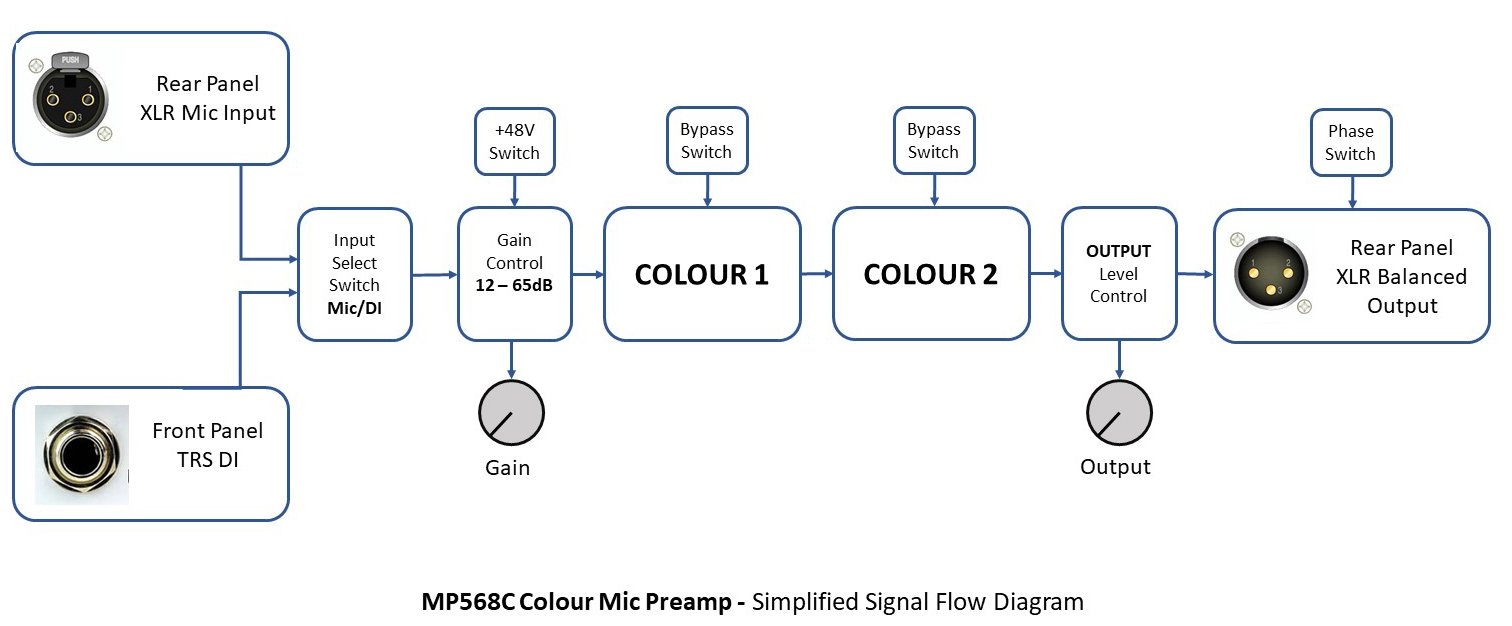
MP568C Simplified Signal Flow Diagram
Please take a moment to become familiar with the signal flow diagram. It is important to understand how the MP568C preamp works.
The input signal can be applied to the rear panel XLR mic input or to the front panel DI. Use the Mic/DI switch on the front panel to select the source. The Gain Control sets the gain level for mic input and the DI which is in the same gain range as the Mic input.
The colour modules are connected in series. There is no other way to configure the colour modules. The Output Level control knob controls the signal from the colour modules. It should be used to adjust the overall output level from the MP568C to avoid overdriving the EQ section and the next audio stage.
The Microphone Preamplifier Section.
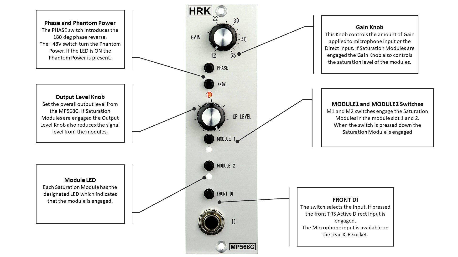
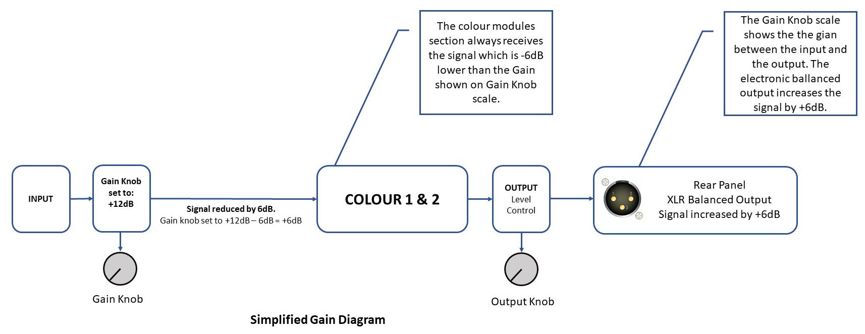
GAIN Knob controls the total gain of the MP568C for Microphone and Direct Input. Values shown on the Gain Knob scale are approximately equal to the total gain of the MP568C from the input to the output. The gain range for the microphone is from +12dB to +65dB. The signal sent to the colour section is always 6dB lower than the total gain set by the GAIN Knob.
NOTE: On higher gain setting (+40 – +65dB) the noise floor may be audible. This is normal at higher gain levels.
The Phantom Power 48V LED indicates the presence of the +48V on the 500 rack rear panel microphone input. The LED is connected to the +48V power supply rail. If the LED is not working it may indicate the failure of the rack main power supply.
The Phantom Power switch – turns ON and OFF the Phantom +48V supply voltage. The UP switch position enables the Phantom supply – the 48V LED is ON.
Phase Inverse switch – INV – inverses the phase of the output signal from the MP568C. The UP switch position inverses the output signal phase.
Colour Section.
The OUTPUT knob sets the total output level from the colour section which is passed to the EQ section. In the 12 o’clock knob position the total output signal level from the MP568C is attenuated by -6dB.
The OUTPUT knob is not a Blend Knob! It is simply a volume control. At the min/left position, the signal will disappear completely. At the max/right position, the signal will be on its maximum level. Colour modules are connected in series. No parallel operation of colour modules is possible. Please see the signal flow diagram.
C1 and C2 switch enables the colour slot 1 and 2.
The Output Section.
The default position of the Output Knob is the max right position. The Output Knob should be used to fine-tune the output signal level from the Colour Preamp to avoid overdriving at the next audio stage such as the audio interface. It is not recommended to set the mic input to high gain while reducing the output level.
Such a setting will overdrive the mic input and the colour modules, it will also increase the noise floor and produce overall unpleasing results. Most of the colour modules will produce the best results if driven with a moderate amount of gain or signal level.
For example, The British Console and the Discrete Line Driver will produce NEVE1073 like effect if driven at approx. 0.5% THD, which is far away from the audible distortion level which occurs at approx. 5% THD. It means also that the optimal output level from the colour mic preamp should peak out on DAW meter at the max of -6dB (-10dB is recommended) to avoid digital clipping.
© 2025 HRK Shop
User Information. This page uses cookies files to process the orders and deliver a better user experience.


