SM2558 USER MANUAL
Introduction.
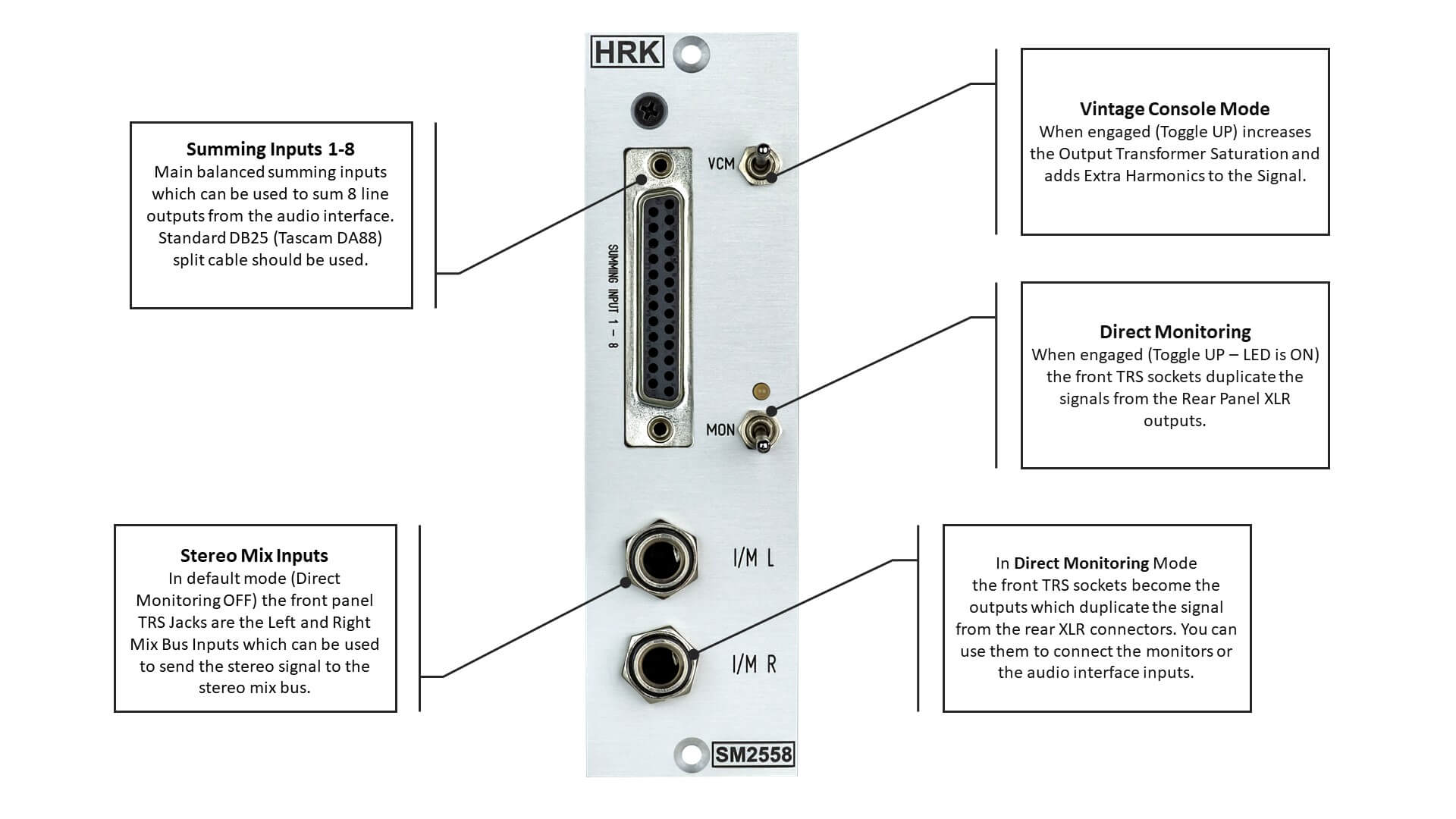
The SM25584 is an Active Stereo Discrete Summing Mixer unit which fits in a single 500 rack space.
The SM2558 has a total of 10 summing inputs which can be used to mix any music material in the Outside-the-Box Analogue Domain.
The Signal Routing.
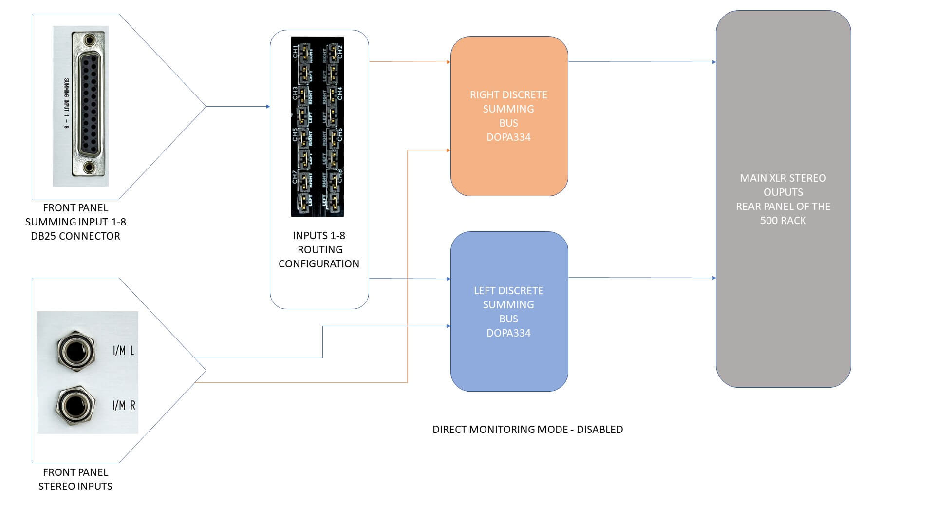
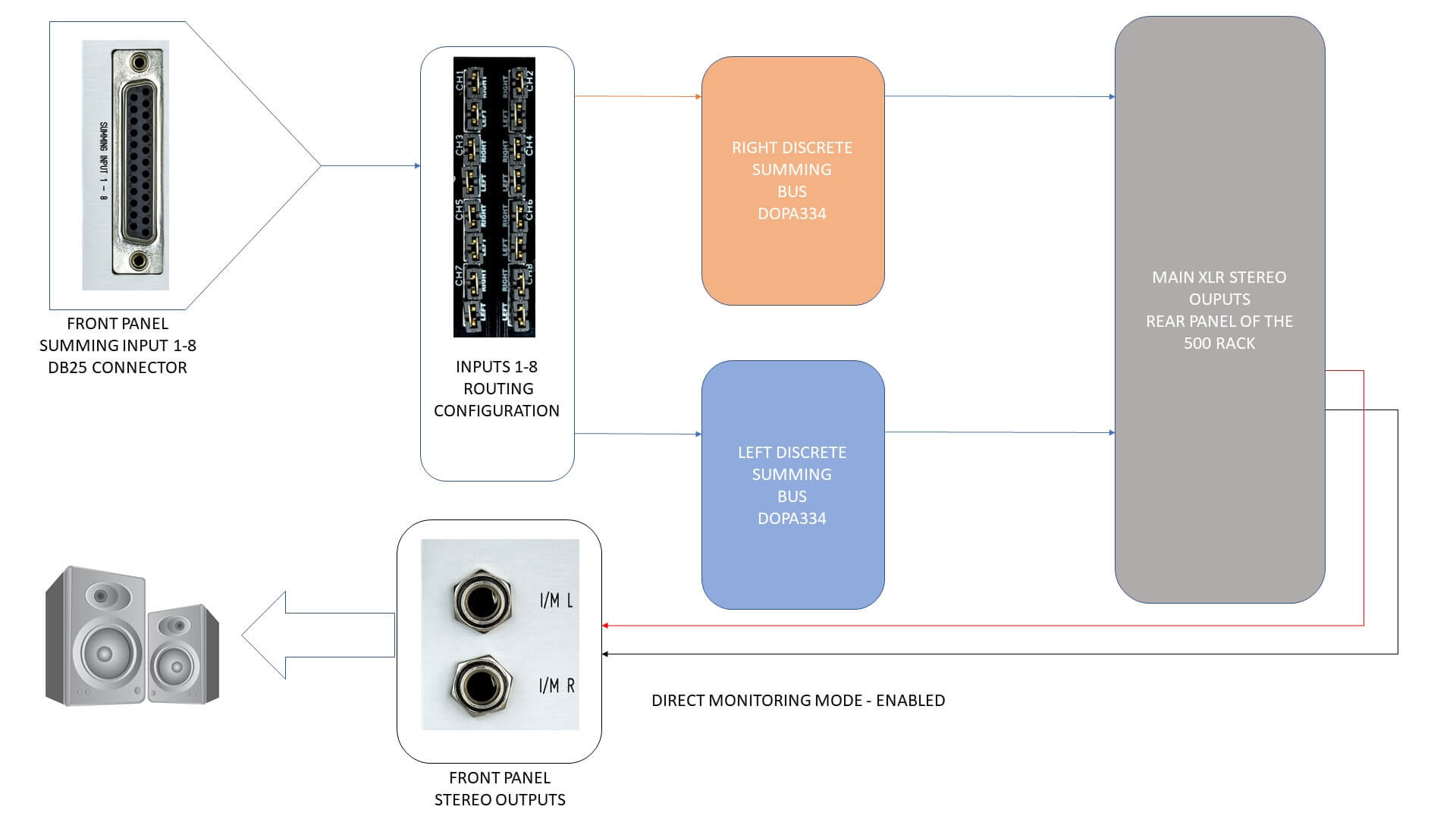
The picture below shows the default mode signal flow diagram – Direct Monitoring DISABLED. The signals from the front panel Summing Input 1-8 are routed with the jumper matrix, summed in the LEFT or RIGHT summing bus and passed to the 500 rack rear panel main XLR connectors.
In this mode, the front panel TRS inputs can be used as the additional stereo summing inputs.
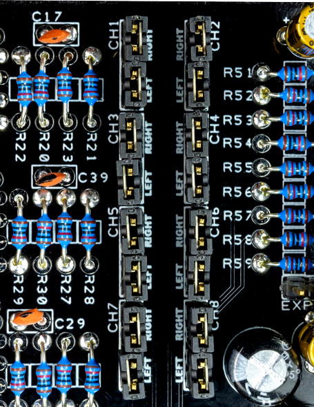
The Front Panel Summing Inputs 1-8 can be routed with the PCB jumpers to LEFT, RIGHT or LEFT + RIGHT summing bus. Use the Summing Matrix to set the desired configuration. The additional stereo front pannel TRS inputs are fixed to Left and Right summing buses.
Before deciding on the input signals routing, you should design the configuration of the mix stems, based on how many line outputs your audio interface has available. The interface with 8 line outputs allows the use of all 8 Summing Inputs.
How to use the Summing Matrix.
If you wish to send the Summing Input 1 to the right + left mix bus (MONO configuration), two jumpers should be inserted in the CH1 section. One jumper in the position CH1-RIGHT and the second jumper in the position CH1-LEFT. In such configuration, the Summing Input 1 can be used to mix a MONO track.
EXAMPLE: The MONO kick drum is mixed only with Summing Input 1. Both jumpers should be inserted – CH1-RIGHT and CH1-LEFT. As a result, the track with a kick drum will be summed in MONO, to the left + right output channels. The level of the kick drum will be equal in Left and Right output channels of the SM2558. In this configuration, the stereo panning is not possible.
| MONO Configuration Example | |||
| Summing Input – CH | LEFT | RIGHT | SM2558 OUTPUT |
| 1 | J | J | LEFT+ RIGHT |
(J) = Jumper inserted
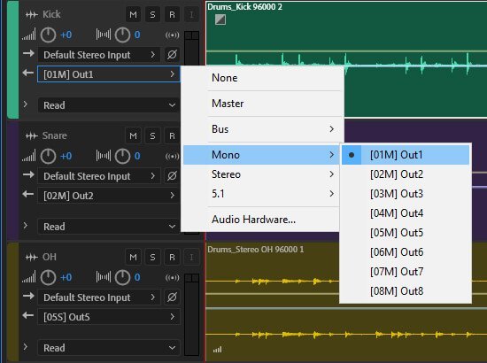
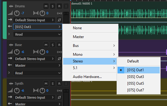
The example of the track settings in the DAW is shown below.
If you wish to send the Summing Input 1 ONLY to right mix bus, one jumper should be inserted in the position CH1-RIGHT. If you wish to send the Summing Input 1 ONLY to left mix bus, the jumper should be inserted only in position CH1-LEFT. To mix the stereo track, two Summing Inputs have to be used.
EXAMPLE: To mix the stereo drums track with Summing Input 1 (Left Channel) and Summing Input 2 (Right Channel), one jumper should be inserted in the position CH1-LEFT and the second jumper should be inserted in the position CH2-RIGHT. As a result, the track with the stereo drums will be summed to the left and to the right output channel. The drums track will be mixed in stereo. Any changes done to the stereo image in the DAW will be passed to the main Left and Right outputs of the SM2558.
| STEREO Configuration Example | |||
| Summing Input – CH | LEFT | RIGHT | SM2558 OUTPUT |
| 1 | J | – | LEFT |
| 2 | – | J | RIGHT |
(J) = Jumper inserted, (-) = Jumper removed
The example of the track settings in the DAW is shown below.
Examples of setup configurations:
| FOUR TRACKS STEREO CONFIGURATION | |||
| Summing Input – CH | LEFT | RIGHT | SM2558 Output |
| 1 | J | – | LEFT |
| 2 | – | J | RIGHT |
| 3 | J | – | LEFT |
| 4 | – | J | RIGHT |
| 5 | J | – | LEFT |
| 6 | – | J | RIGHT |
| 7 | J | – | LEFT |
| 8 | – | J | RIGHT |
(J) = Jumper inserted, (-) = Jumper removed
In this configuration, all summing inputs are set to stereo mode. The output of each track in the DAW should be sent to the stereo output or stem/sub-group. If more than four tracks are used in the mix, some of the least important tracks can be sent to the same output stem or sub-group.
Example: The leading stereo vocal uses the output/steam 1+2, the stereo guitar uses the output/steam 3+4, the percussion summed in the stereo sub-group uses output/steam 5+6, the stereo reverb/effect returns use the output/steam 7+8.
| SIX TRACKS MIXED STEREO/MONO CONFIGURATION | |||
| Summing Input – CH | LEFT | RIGHT | SM2558 OUTPUT |
| 1 | J | J | LEFT + RIGHT |
| 2 | J | J | LEFT + RIGHT |
| 3 | J | J | LEFT + RIGHT |
| 4 | J | J | LEFT + RIGHT |
| 5 | J | – | LEFT |
| 6 | – | J | RIGHT |
| 7 | J | – | LEFT |
| 8 | – | J | RIGHT |
(J) = Jumper inserted, (-) = Jumper removed
In this configuration, summing inputs are set to stereo/mono mixed mode. The output of each track in the DAW should be sent to stereo or mono output. If more than six tracks are used in the mix, some of the least important tracks can be sent to the same output stem or sub-group.
Example: The mono leading vocal uses the mono output/steam 1, the mono leading guitar uses the mono output/steam 2, the mono base guitar uses the mono output/steam 3, The mono backing vocals use the mono output/steam 4, the percussion summed in the stereo sub-group uses output/steam 5+6, the stereo reverb/effect returns use the output/steam 7+8.
Note: If your audio interface has more than 8 line outputs, the TRS inputs available on the front panel of the SM2558 can be used as an additional stereo mixing inputs.
Direct Monitoring Mode
In this mode, the front panel TRS sockets are converted to the outputs which duplicate the signal from the main 500 rack XLR outputs. Such a mode is very useful if the audio interface has a limited number of line outputs. The monitors can be connected to the front panel TRS sockets or the 500 rack XLR outputs.
The MON switch converts the front panel TRS sockets into the Direct Monitoring outputs. The Direct Monitoring function allows to edit, listen and process the mix at the same time without the latency.
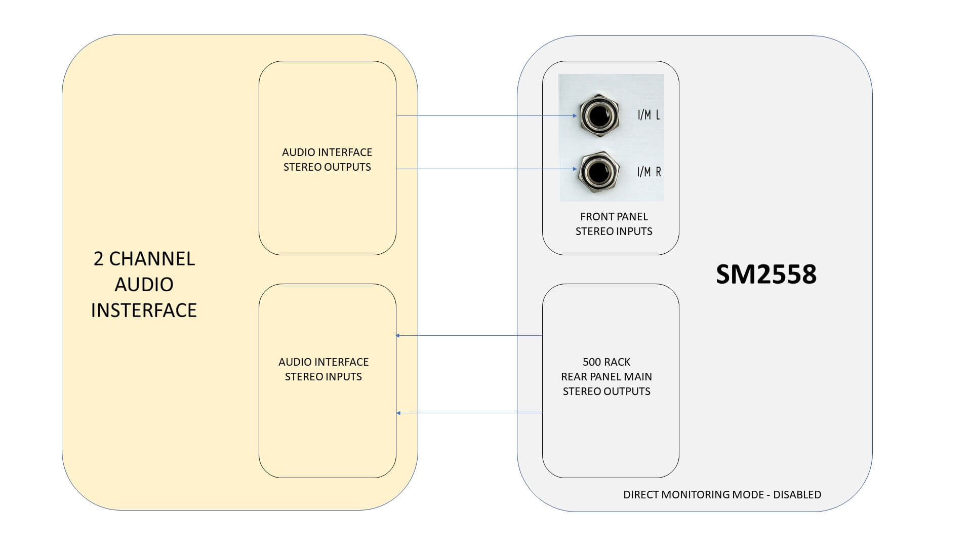
Use of the SM2558 with a simple two-channel audio interface
The SM2558 can be used even without the D25 split cable, with a simple two-channel audio interface. The front panel TRS inputs can be used to process any stereo signal.
To use the SM2558 with two-channel audio interface the Direct Monitoring Mode has to be DISABLED – toggle switch in the LOW position – the LED OFF.
DB25 audio split connection cable.
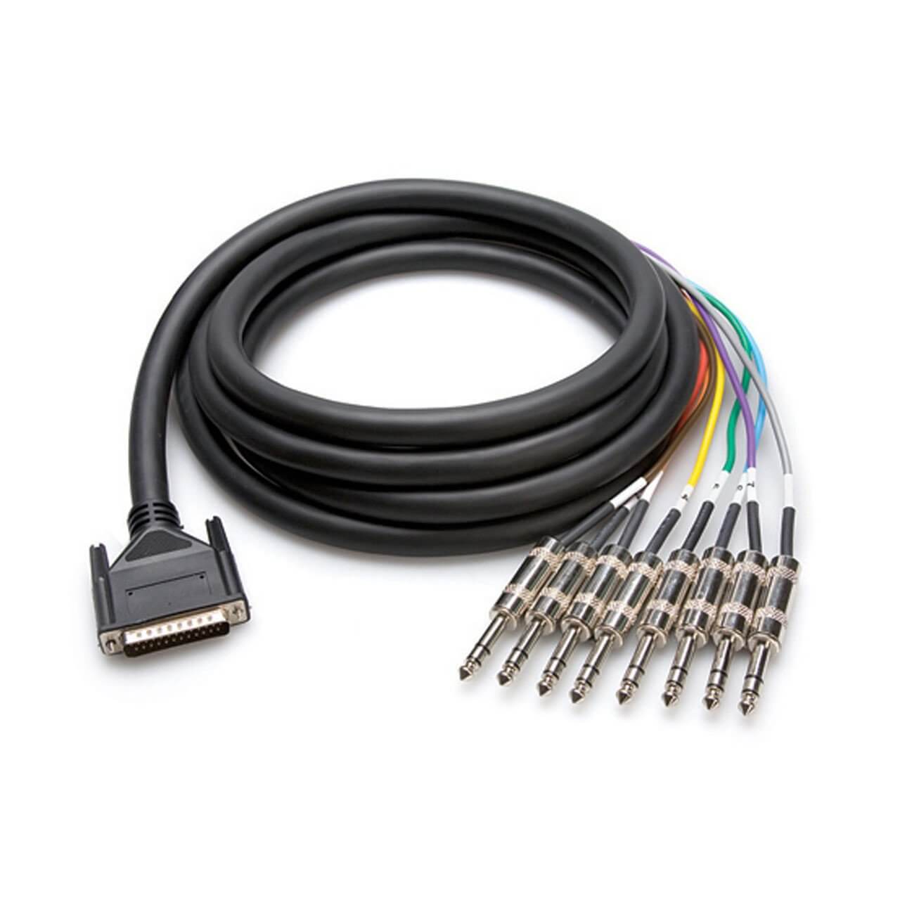
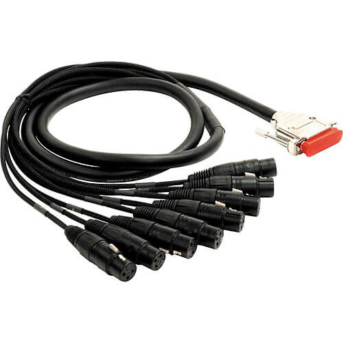
To connect the SM2558 with the audio interface, the DB25 audio split cable has to be used.
You should choose the correct type of DB25 cable connectors (TRS or XLR), depending on what type of the audio interface you use.
You can use any Pro Tools & Tascam DA88 standard 25-way split cable to connect the SM2558 with the audio interface.
25 Way Connector Pinout:
| Balanced Summing Inputs 1 – 8 | |||
| Input | Shield | Hi | Lo |
| 1 | 25 | 24 | 12 |
| 2 | 11 | 10 | 23 |
| 3 | 22 | 21 | 9 |
| 4 | 8 | 7 | 20 |
| 5 | 19 | 18 | 6 |
| 6 | 5 | 4 | 17 |
| 7 | 16 | 15 | 3 |
| 8 | 2 | 1 | 14 |
The use of the 500 single slot in a stereo configuration.
It might be counter-intuitive to use a single slot of the 500 rack in stereo mode. Nonetheless, it is absolutely possible and completely safe.
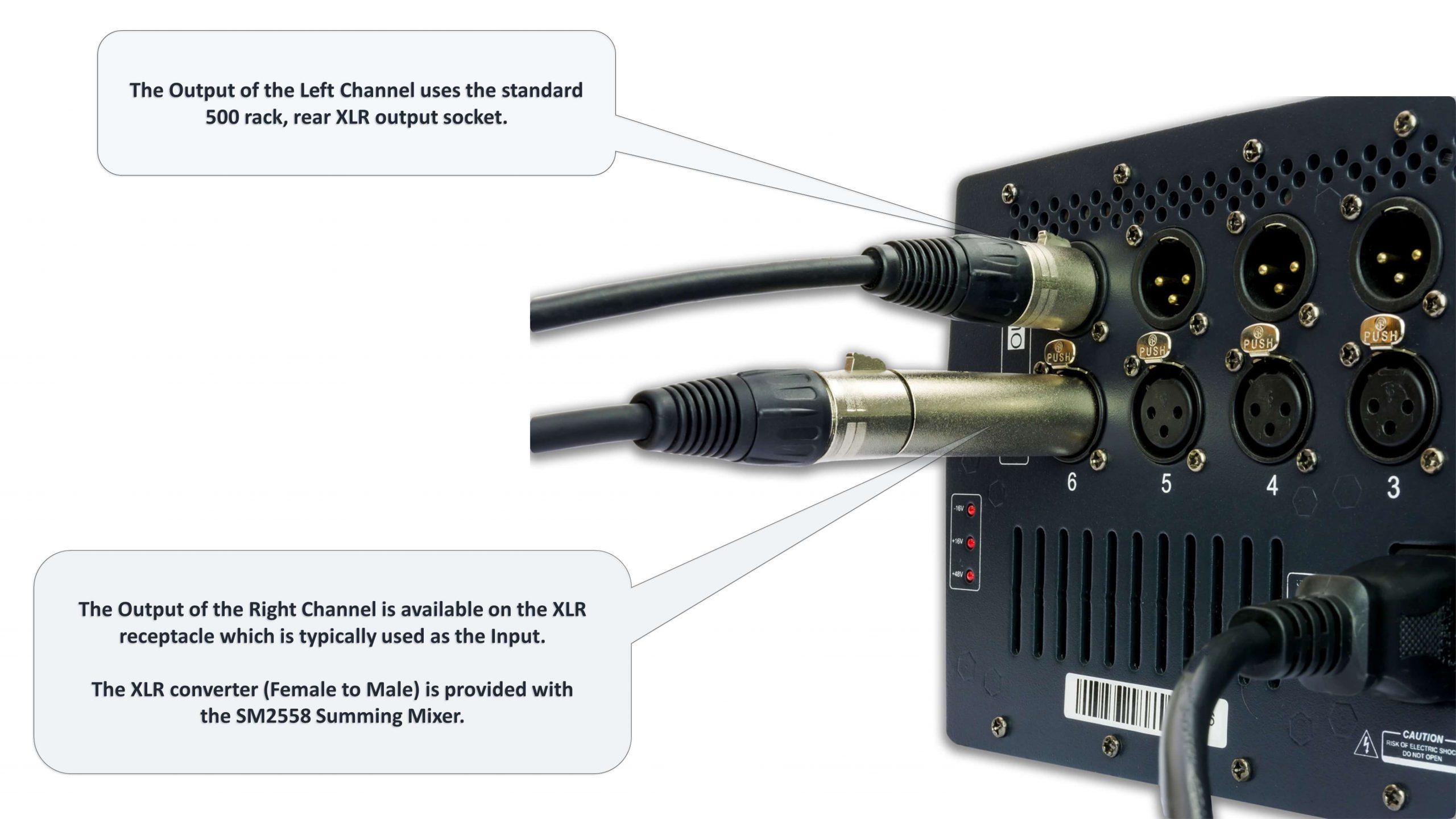
The 500 rack rear panel XLR input connector is nothing more than a straight-wire connection between the XLR socket and the 500 module PCB edge connector. Therefore, it can be easily converted to the output with the included XLR male-to-male adapter.
The picture below shows the arrangement of the rear panel XLR connectors. The XLR male-to-male adapter is included with the SM2558.
NOTE: If your 500 rack has any built-in extra routing features, remember to disable any routing options before the use of SM2558.
Connecting the SM2558 Expander
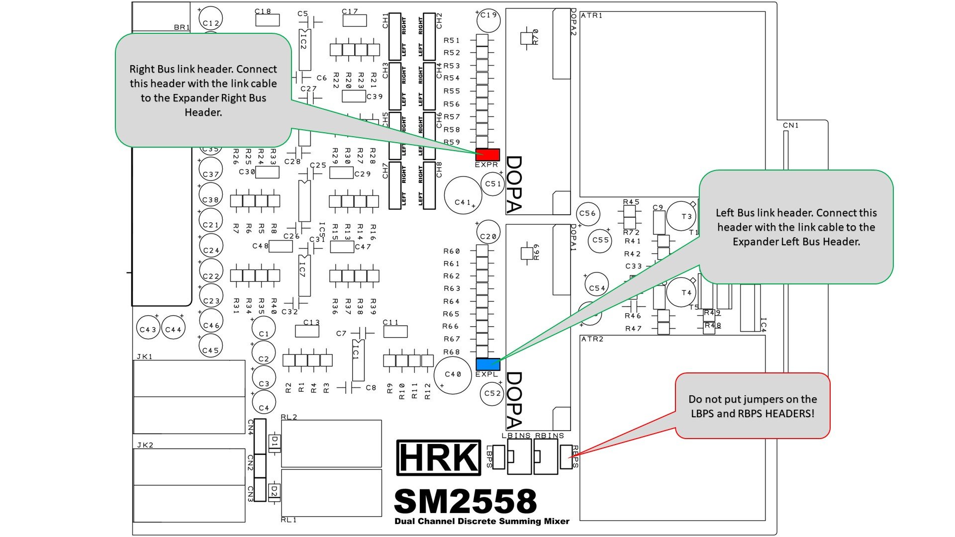
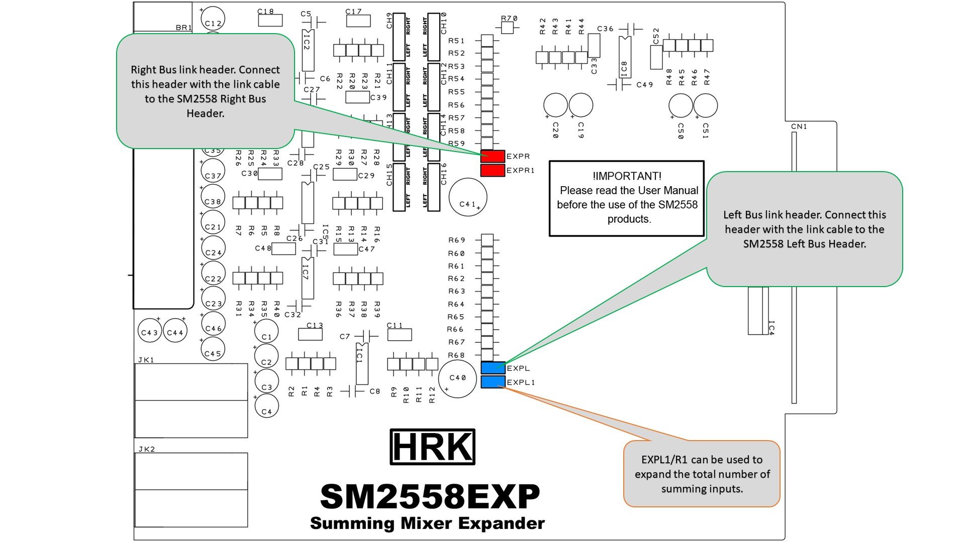
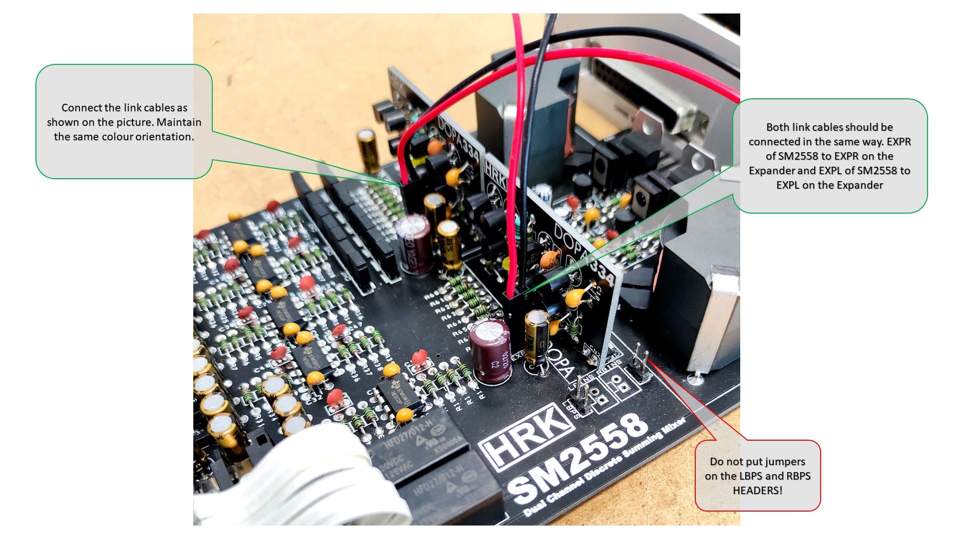
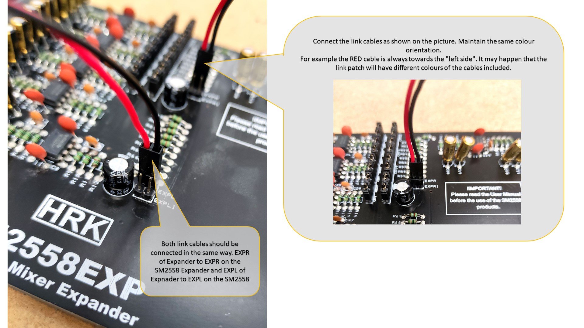
The SM2558 Expander has to be connected with the SM2558 unit using the included cables. First you have to locate the connection headers on the SM2558 and the SM2558EXP unit. Please see the pictures below.
Note: It is possible to connect more Expander units in the daisy chain configuration. EXPL1/R1 can be used to expand the total number of summing inputs.
Next, you have to connect link cables as shown in the pictures below. Please maintain the same colour orientation for the SM2558 and the Expander unit. For example, the RED cable is always towards the “left side”. It may happen that the included link cable will have different colours of the individual cables.
Return to the SM2558 page ->
© 2025 HRK Shop
User Information. This page uses cookies files to process the orders and deliver a better user experience.


